Route
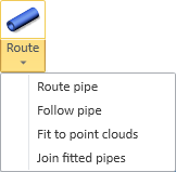
On the Piping tab, in the Pipe group, the Route menu includes the following tools.
Route pipe
You can route new pipes in the 3D model.
Do the following:
-
Optionally, select the system for the new pipe from the Model Tree pane.
-
Select Piping tab > Pipe group > Route > Route pipe.
-
Pick the start point of the new pipe (see Define the start point), and press Enter.
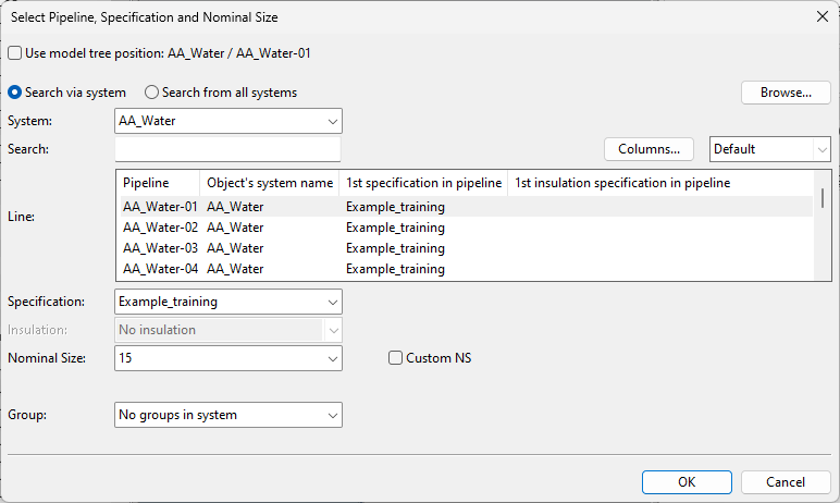
If you are creating a completely new pipe, the Select Pipeline, Specification and Nominal Size dialog opens.
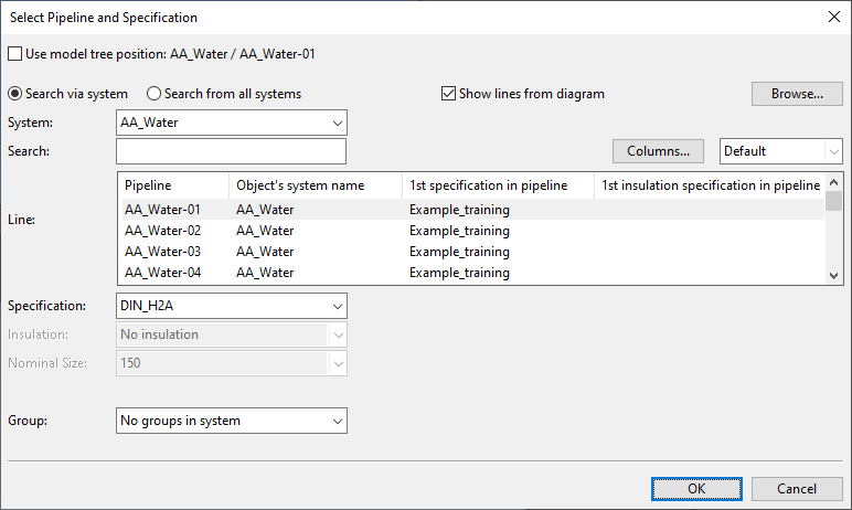
If you are continuing routing from an existing pipeline, the name of the dialog is Select Pipeline and Specification.
-
Specify the pipe settings.
 Show/hide details
-
System – Select the system for the model object. The available lines are listed in the Line pane. If nothing is found, select Search from all systems.
-
Line – Select the pipeline to use.
You can use the Search field to find the required line. Also regular expressions are supported.
Show/hide details
-
The columns that are searched are predefined. Note that the search string can also be found from a column that is not currently visible: click Columns to define which columns to show.
-
The search string can be found from any part of the target string, and the search is not case-sensitive.
Search string…
Finds…
line
strings that contain LINE, such as 'MyLine-01'
-
You can use a dot to represent a single required character.
Search string…
Finds…
....line-01
strings where LINE-01 is preceded by at least four characters, such as 'AA_MyLine-01'
-
You can use advanced regular expressions if you add R: to the beginning of the search string.
Search string…
Finds…
R:[ad]
strings that contain A or D, such as 'DIN_H2A'
R:[a-d]
strings that contain A, B, C or D, such as 'CW-001'
R:^k
strings that start with K, such as 'K51'
R:[\s]
(or just R: followed by one space character)
strings that contain a whitespace character, such as 'My Line 01'
Note: When using P&ID integration, the dialog only shows the systems and lines that have the attribute Use In Plant Modeller set to 'Allow' and that are selectable in this context (based on the connectivity information defined in diagrams). To show all pipelines, clear the option Show lines from diagram.
-
-
Specification – If the line allows multiple piping specifications, select the one to use.
-
Insulation – If the line allows multiple insulation specifications or not using insulation, select the appropriate option.
-
Nominal Size – If nominal size can be changed, select the size from the list or select Custom NS and type the size to use. The default value is the last used nominal size, and the list only contains sizes that have material defined in the piping specification.
-
Group – Select whether to assign the model object to an existing or new group.
-
Click OK.
-
-
If the new pipe is connected to a Standard Component that uses a different specification with different requirements for bolt set or gasket, you are prompted to select the specification from which to take the joint materials. Click the name of the specification that you want to use.
-
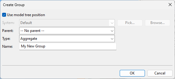
If you chose to create a new group, the Create Group dialog opens. Define the properties of the group to be created, and click OK.
-
Insert straight or curved pipe segments along the intended route, and add any components in the order in which they appear along the route. The description, dimensional description, material, and standard specified for the component in the corporate catalog are displayed in the message pane.
Show/hide details
-
Navigate to a route point and press Space to complete the given pipe segment. By default, each new segment uses the pipe centerline as the reference point, but you can use Select reference point to route the current segment by using one of the pipe quadrant points as the reference.
-
You can change the direction of the pipe by selecting the direction from a graphical tool. See Use routing direction assist for details.
-
You can follow the route of another pipe by using the Follow another pipe command.
-
You can use the commands Undo (U) and Redo (Ctrl+Y) to remove or restore pipe segments and components, if needed. Undoing the first added segment cancels the routing operation.
-
If P&ID integration is in use, there is a visual aid ("candy bar") that shows where the pipe you are routing should be connected.
-
-
End the route as applicable:
-
Connect (P) or Join (J) the end point to a node in an existing piping part.
Note: If your project uses P&ID integration and you connect or join the end point to a Pipe, Standard Component, or Equipment, the program validates the connection using connectivity information obtained from the P&I diagram.
-
Press Enter or Esc to accept the piping parts you have inserted so far.
-

Follow pipe
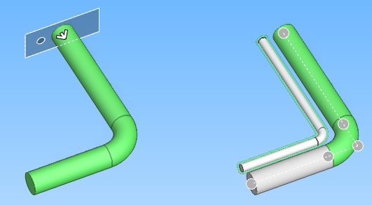
You can route a new pipe by following the route of an existing pipe. If the existing pipe has supports, you can position the new pipe so that once supports are added to the new pipe, the supports of both pipes are aligned.
Tip: Go to YouTube to watch a video on this feature!
Do the following:
-
Select Piping tab > Pipe group > Route > Follow pipe.
-
Select the system, pipeline, specification, insulation, and nominal size, and click OK.
-
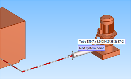
Select the pipe to follow: pick a straight piping part near the end where you want to start routing the new pipe, and press Enter. The Define Distances dialog opens, and the work view shows the starting point and routing direction.
-
Select Follow to the other direction if starting between two straight piping parts and the routing direction is currently wrong.
-
If the pipe to follow has supports, you can position the new pipe so that its supports, once added, will be aligned with the supports of the followed pipe.
Show/hide details
-
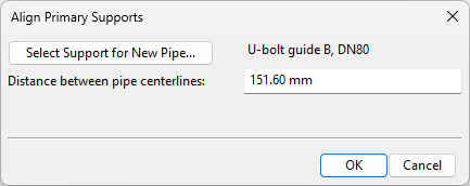
Click Align Supports. The Align Primary Supports dialog opens.
-
Click Select Support for New Pipe, select the support that the new pipe will be using, and click OK.
-
Adjust the Distance between pipe centerlines as required.
-
Click OK.
-
-
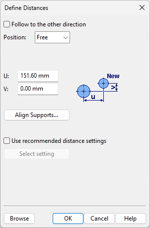
If not aligning the pipes by their supports, you can define the starting point of the new pipe in the following ways:
-
Position – Select on which side of the existing pipe to position the new pipe.
-
SideA, SideB – New pipe starts from the given side of the existing pipe.
-
Top, Bottom – New pipe starts from above or below the existing pipe.
-
Free – New pipe starts from the defined U,V distance.
Alignment – If the new pipe is of different size and 'Position' is not 'Free', select whether to align the new pipe with the existing pipe based on their centerlines or a specific side.
-
-
U, V – Specify these values to define the distance between the pipe centerlines manually.
-
Use recommended distance settings – Select this option and click Select setting to take the U distance from a Follow pipe settings configuration.
-
-
Click OK to accept the starting point.
-
Route the new pipe by doing one of the following:
-
Use Follow pipe to end (M) to route the whole pipe at once.
-
Use Next segment (Space) to insert one segment of the new pipe at a time.
-
-
Press Enter (or Space, if all possible segments have been added) to accept the new pipe.
Fit to point clouds
Select Piping tab > Pipe group > Route > Fit to point clouds to fit straight pipes into a point cloud.
See Fit pipes in the point cloud tutorial for more details.
Join fitted pipes
Select Piping tab > Pipe group > Route > Join fitted pipes to build a complete pipe segment from disconnected, straight pipe parts that have been modeled in a point cloud.
First the tool prompts you to select and accept pipe parts, one at a time. The parts do not need to be in a straight line, but there needs to be enough space between them to create the required shape. When you accept the set of parts, the gaps are filled and the parts are joined to form a single pipe part. Seams and geometry points remain between the joints.

See Fit pipes in the point cloud tutorial for more details.